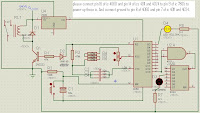
Circuit Diagram shown is the Week Timer that give a high signal once in a week.
times. IC 4060 IC counts 24 hrs, these 24 hrs are counted by another counter 4024 IC. So total makes a week counter.
WORKING:
The IC 7805 is a fixed 5V regulator and is used to give fixed 5V dc to the ICs.
The CMOS IC-4060 is a 14 bit binary counter with a built in oscillator. We set the timing by setting the frequency of oscillator.
For time controlling we use the formula:
T = R x C
where; C in this circuit is the combination of C2, C3, C4
and R is the combination of R4, R5, R6 and Potentiometer. Potentiometer is used just to set the accurate timing.
Now to calculate timings consult table given below.

We want a period of 24 hrs. so first convert 24hrs into seconds.
24hrs x 60 x 60 = 86400 seconds
As we want pin 3 high after 86400s so from the setup table divide this value by 1024
so, 86400 / 1024 = 84.4s. Therefore set pot at a position so that yellow led blink after 84.4s. This will give an output at pin 3 after 24hrs.
The output of 4060 is in negative so to make it positive, we inverted using NAND gate IC 4011.
Truth table for NAND gate is:

Table shows that when same input, output will be inverted. Thats what happening in the circuit. The inverted output is given to the ripple counter IC 4024. It will give output at pin 9 on 7 counts.
So 7 times 24 hrs will result in a week counter.
APPLICATIONS:
The timers are use in every type of industry.
They can be used for various applications.
times. IC 4060 IC counts 24 hrs, these 24 hrs are counted by another counter 4024 IC. So total makes a week counter.

WORKING:
The IC 7805 is a fixed 5V regulator and is used to give fixed 5V dc to the ICs.
The CMOS IC-4060 is a 14 bit binary counter with a built in oscillator. We set the timing by setting the frequency of oscillator.
For time controlling we use the formula:
T = R x C
where; C in this circuit is the combination of C2, C3, C4
and R is the combination of R4, R5, R6 and Potentiometer. Potentiometer is used just to set the accurate timing.
Now to calculate timings consult table given below.

We want a period of 24 hrs. so first convert 24hrs into seconds.
24hrs x 60 x 60 = 86400 seconds
As we want pin 3 high after 86400s so from the setup table divide this value by 1024
so, 86400 / 1024 = 84.4s. Therefore set pot at a position so that yellow led blink after 84.4s. This will give an output at pin 3 after 24hrs.
The output of 4060 is in negative so to make it positive, we inverted using NAND gate IC 4011.
Truth table for NAND gate is:

Table shows that when same input, output will be inverted. Thats what happening in the circuit. The inverted output is given to the ripple counter IC 4024. It will give output at pin 9 on 7 counts.
So 7 times 24 hrs will result in a week counter.
APPLICATIONS:
The timers are use in every type of industry.
They can be used for various applications.
Digital timer has shown clear and precise characteristics. It is that time of the digital pulse signal, after decoding by the digital device with a digital display tube display.
ReplyDeleteNice blog...
ReplyDeleteThanks for Sharing..
Data Logger, Digital Timer, Humidity meter Controller, Digital Counter